Views: 38 Author: Site Editor Publish Time: 2025-08-18 Origin: Site
Q1. What is “Three-Stage Protection”?
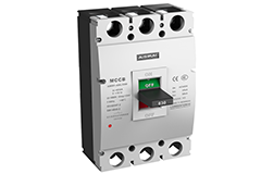
Three-stage protection is a common electronic trip combination in MCCBs (Molded Case Circuit Breakers):
Long Time (L): Protects against overload, controls temperature rise, inverse time only.
Short Time (S): Protects against medium-level short circuits, provides selective coordination, fixed delay or adjustable I²t delay.
Instantaneous (I): Protects against high-level short circuits, limits arc energy, no delay or very short delay.
Q2. Why must all three stages be set? Why not rely only on Instantaneous protection?
Long Time: Prevents conductors and loads from overheating due to prolonged overload.
Short Time: Ensures selectivity between upstream and downstream breakers at ~100 ms level, minimizing the outage area.
Instantaneous: Clears severe faults within 1–2 cycles, reducing thermal and mechanical stress.
If only Instantaneous protection is set, the risks are:
Small overloads go undetected, causing cable aging and damage.
Upstream breaker trips directly, resulting in a “blackout” of the whole system instead of just the faulty load.
Motor starting currents may be mistaken for faults, leading to nuisance tripping.
Q3. What data should be prepared before settings?
| Parameter | Source |
|---|---|
| In | Breaker frame/rated current (nameplate) |
| Ib | Design load current (electrical calculation) |
| Iz | Cable continuous current capacity (cable manual) |
| Isc min / Isc max | Minimum/maximum short-circuit current (short-circuit study, optional) |
| Starting inrush (for motors) | Measurement (preferably full-load test) |
Q4. How to set Long Time (L) current Ir?
Must satisfy Ib ≤ Ir ≤ Iz. Typical practice:
Cable protection priority: 0.8 In ~ 0.9 In.
Large load fluctuation: 0.9 In ~ 1.0 In.
General principle: As high as cable rating allows; short-circuit faults should be handled by S and I, while L is mainly for overload.
If DOL motor starting current ≥ 6 Ir, increase Ir or extend the delay time.
Q5. How to set Long Time delay Tr?
IEC recommendation: trip in 3 – 10 s at 6 × Ir.
For motor starting coordination: Tr ≥ 1.2 × maximum starting time.
Q6. How to set Short Time (S) pickup Isd?
IEC/GB adjustable range: 1.5 Ir – 10 Ir.
Branch circuits: 2 – 4 Ir (to avoid nuisance tripping from inrush).
Main feeders: 5 – 8 Ir (allowing upstream to wait for downstream).
Overlay upstream/downstream TCC curves to ensure at least 0.2 s selectivity margin at 0.1 s.
Q7. What is a “safe zone” for Short Time delay Tsd?
With fuses or small-frame MCCBs: 0.1 – 0.2 s preferred.
With ATS/Bus-tie/transfer systems: can be shortened to 0.05 – 0.04 s.
Q8. How to set Instantaneous (I) pickup Ii for fast clearing without miscoordination?
Lower limit: Ii ≤ 0.8 × Isc min, ensuring even minimum faults are cleared.
Upper limit: Ii > downstream S pickup peak, preventing upstream from tripping first.
Thermal-magnetic type: usually fixed at 10 – 15 In; electronic type adjustable from 2 – 15 Ir. Delay = 0 (generally non-adjustable).
Since Instantaneous has no delay, it is the most sensitive stage. A practical rule: set Ii ≥ 1.5 × Short Time pickup current.